Multi-Chassis Link Aggregation Groups, often abbreviated MLAG, but also known under the acronyms CLAG, MC-LAG, MCT, SMLT, VLT, or vPC, provide a relatively simple method for active/active Layer 2 (Ethernet) redundancy. The usual implementation is based on two switches that work with independent control planes and use some (proprietary) protocol to negotiate MLAG operations.
This article assumes some basic familiarity with MLAG functionality.
(The IEEE 802.1AX-2020 standard for link aggregation contains an MLAG-like mechanism called Distributed Resilient Network Interconnect (DRNI). DRNI is supposed to revert to independent operation, including changing to different individual LACP system IDs, when the Intra-Relay Connection (IRC) fails. This avoids a split brain situation, and thus avoids the problem described on this web page. But this risks other problems, e.g., a system connected to a DRNI LAG might place all physical links into an error-disabled state when the remote LACP system ID changes[1], resulting in total connectivity loss.)
Basically every vendor of networking equipment, i.e., switches in the context of MLAG, uses different terminology to describe more or less the same thing. I will use the terms MLAG functionality, MLAG peer switches, MLAG, MLAG port, peer link, and split brain as follows:
In a split brain situation, ARP resolution by the MLAG peer switches may no longer work reliably. This article examines this particular problem.
This potential problem in a split brain situation, i.e., when
the peer link between the two MLAG peer switches of an MLAG pair
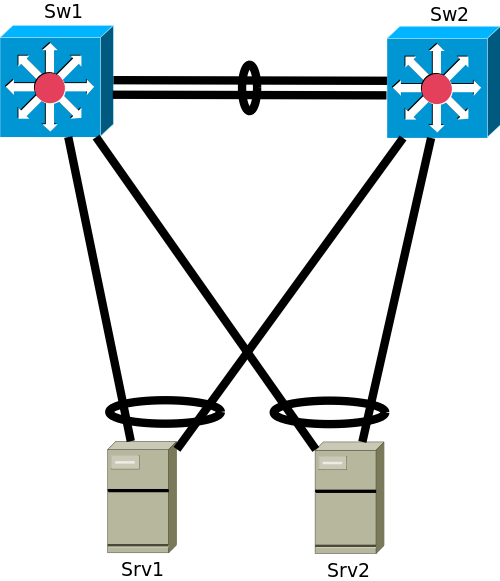
fails, pertains to a simple MLAG setup comprising just two switches
Sw1 and Sw2, and two servers Srv1
and Srv2. Two servers provide some motivation for first
hop gateway functionality on the MLAG peer switches, because they could
be in different VLANs with different subnets.
More compliacted setups, e.g., connecting a group of MLAG peer switches via MLAG to another group of MLAG peer switches, have this problem, too.
As long as there are no link failures and no single-attached devices (also known as orphan ports), the connection between the two switches of an MLAG pair is nearly unused. Most data frames received by one of the MLAG peer switches are forwarded to another local MLAG port.
But as soon as the MLAG peer switches start to perform some Layer 3 (IP) functionality, the peer link is required for normal operations even without any partial MLAG failures. For example, ARP resolution by one of the MLAG peer switches may require the response frame to traverse the peer link, depending on the load sharing decision performed locally on the responding device.
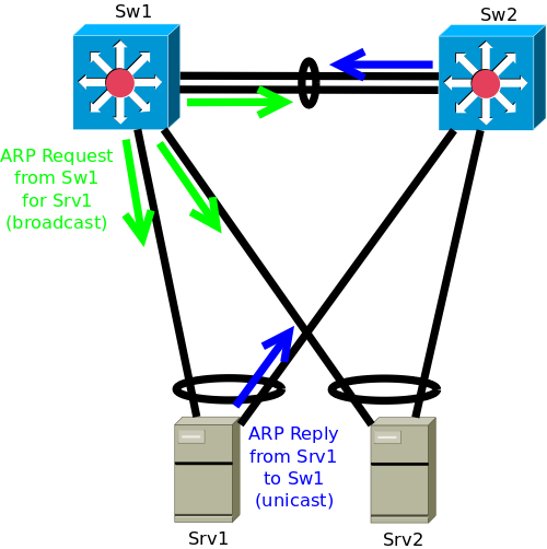
If the peer link between the two MLAG peer Switches fails, ARP resolution may fail, inhibiting some IP communication.
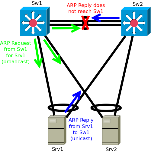
Device local load sharing decisions determine if ARP resolution works or fails for some other device. Some IP communication will work, some will fail. Mitigations for this problem exist and should be considered for any MLAG deployment.
One way to mitigate this problem (and similar ones) is to disable the MLAG ports of one of the MLAG peers in a split brain situation. This requires defining one of the peers to fulfill a primary role, and the other to fulfill a secondary role. Then the secondary MLAG peer is configured to disable its MLAG ports if a split brain situation is detected.
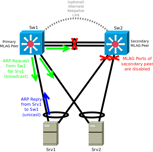
Usually an additional, potentially logical, link between the MLAG peers is established to allow the secondary MLAG peer to distinguish between failure of the MLAG peer link and failure of the primary MLAG peer (this is an additional keepalive connection). An MLAG setup without this additional connection cannot provide mitigation of both the failure of any MLAG peer switch and failure of just the MLAG peer connection. The same basic idea is supported in some switch stacking and many chassis bonding solutions as well.
For external connectivity, MLAG peer switches performing both Layer 2 and Layer 3 functionality are usually connected to other Layer 3 devices, i.e., routers. In order to automatically mitigate (some) failures, this should use a routing protocol.
When all MLAG ports on the secondary peer are disabled after peer link failure (i.e., in a split brain situation), all local end-system VLAN interfaces should go down automatically. Thus local end-system networks should no longer be announced. This is required for this mitigation to work. Thus the combination of single-attached devices with MLAG-attached devices in the same VLAN breaks this split brain mitigation mechanism even for devices connected to MLAG ports.
If the MLAG implementation is combined with an anycast VTEP for redundant server connectivity to a VXLAN fabric, the secondary MLAG peer's anycast VTEP needs to be disabled as well as any (other) MLAG port in a split brain situation. The important parts are both to no longer advertise the anycast VTEP IP into the underlay, and to disable the local anycast VTEP IP interface.
There are alternatives to the above mitigation mechanisms that rely on additional functionality. This additional functionality is less common than an additional keepalive connection with the ability to disable the MLAG ports of the secondary switch.
Another mitigation would be to use the additional keepalive connection for synchronization of ARP cache contents instead of disabling the MLAG ports of the secondary peer.
The other MLAG control protocols should then also use the keepalive link to prevent the split brain even though the data plane is impaired.
If the VXLAN deployment uses a control plane protocol like EVPN, information about MAC address to IP address association can be distributed via this protocol. This not only potentially allows to locally answer ARP requests allowing to suppress ARP flooding to remote VTEPs, it can also mitigate the ARP resolution problem described above as long as the control plane protocol provides this feature and still works correctly after a failure of the MLAG peer link, e.g., via Layer 3 uplinks. This mitigation is a possible replacement for disabling the MLAG ports of the secondary MLAG peer by preventing a split brain situation in the case of a failed MLAG peer link.
In a network comprising more than just two switches, i.e., switches in addition to the MLAG pair (possibly additional MLAG pairs), use of a virtual peer link, i.e., peer link functionality implemented by encapsulating frames for the MLAG peer for transport over the switch's uplinks, allows to treat the MLAG peers equally without primary or secondary designation. If an MLAG peer loses all uplinks, it needs to disable all MLAG ports. As long as at least one uplink of the other peer is still working, the MLAG construct provides connectivity. Direct links between the MLAG peers can function as additional uplinks.
This obviously does not help if there are only direct connections between the two MLAG peer switches and thus no uplinks at all.
It may in general be helpful to disable all downlinks of a switch that has lost all its uplinks in order to signal downstream devices (e.g., servers) to switch to another port (unless there are single-attached devices). Some hypervisor vendors expect this network behavior.
If there are any single-attached devices connected to any of the MLAG peer switches, a failure of the connection between the MLAG peers cannot always be mitigated. Thus the network design should avoid single-attached devices on MLAG peer switches, e.g., by adding additional switches without MLAG functionality to connect all hosts that cannot use an MLAG connection.
A peer link failure results in connectivity problems for single-attached devices. This includes devices connected via MLAG where all links to one of the MLAG peer switches have failed, but at least one link to another MLAG peer switch is still working. This also pertains to a pure Layer 2 setup.
A single-attached device is similar to an MLAG-attached device where all but one of the links have failed. An MLAG construct cannot protect against arbitrary multiple failures, but a single-attached device is equivalent to a dual-attached device where some failure has already occurred, thus the first real failure is actually a multiple failures situation for single-attached devices.
back to my homepage.